7 Common 3D Modeling Mistakes That Lead to Print Failure
When moving from a digital design to a physical object, small errors in the 3D model that are invisible on screen can lead to failures on the build plate. Read about the most common issues that might go by overlooked when designing for 3D printing – and why you’ll want to make sure they are avoided.
Non-Manifold Geometry
A 3D model has to be “watertight” to be printable. Non-manifold geometry occurs when a model has holes, self-intersecting faces, or edges shared by more than two faces. If the slicer software can’t determine which part of the model is “inside” and which is “outside,” it will generate erratic toolpaths, often leading to missing layers or total print collapse.
Wall Thickness is Too Thin
Every 3D printing process has a minimum feature size. In Fused Deposition Modeling (FDM), if a wall is thinner than the nozzle diameter (typically 0.4 mm), the printer may skip that section entirely. Even if it does print, walls that are too thin lack the structural integrity to support the layers above them, resulting in parts that warp, snap, or crumble during post-processing. This can be easily avoided.
Insufficient Bed Contact Area
FDM prints rely on a strong bond with the build plate to stay in place. The same applies to resin-based printing technologies like Stereolithography (SLA), Masked Stereolithography (MSLA/LCD), and Digital Light Processing (DLP).
Models with a very small “footprint” or rounded bottoms are prone to detaching mid-print due to the lateral forces of the extruder or the suction of the resin vat. Adding a flat base or a “brim” in your design can help ensure the part stays anchored, although keep in mind that, if printed in the same material as the model, it might be challenging to remove them cleanly. If in doubt, contact our Customer Success team or add a note to your order for the manufacturer.
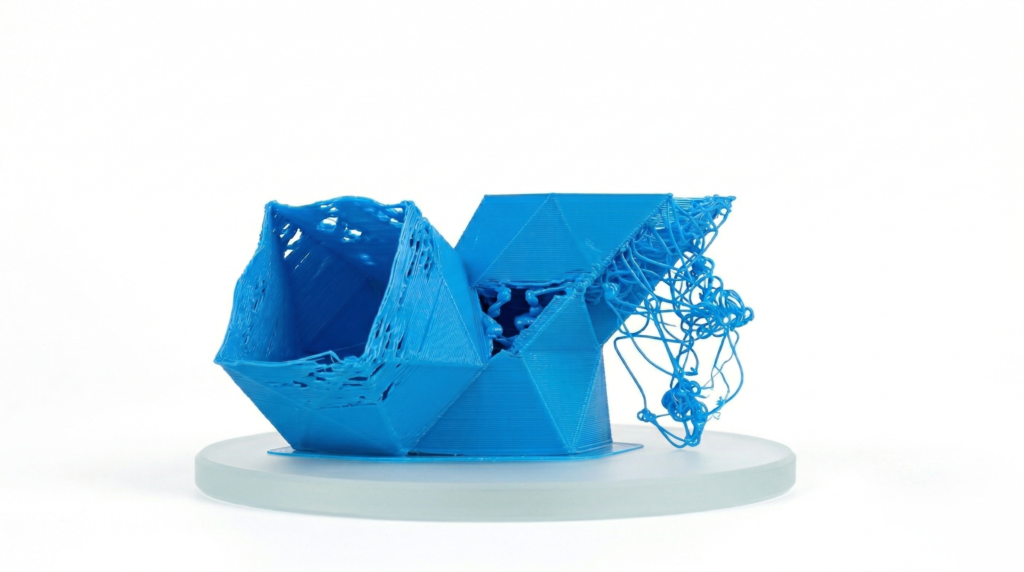
Overlooking the “45-Degree Rule”
While technologies like Selective Laser Sintering (SLS) and Multi Jet Fusion (MJF) are self-supporting, FDM and SLA can’t print into thin air. Designing steep overhangs (greater than 45 degrees) without considering support structures leads to “spaghetti” plastic or drooping resin. If you don’t want to use supports, you must design with chamfers or angles that allow each layer to be partially supported by the one beneath it.
Incorrect Mesh Density
Exporting a model with a low polygon count (e.g. a low-resolution STL) results in “faceted” surfaces where smooth curves look like a series of flat triangles. Conversely, an excessively high polygon count creates massive file sizes that can crash slicer software or cause “stuttering” during the print as the machine struggles to process thousands of tiny movements per second.
Ignoring Material Shrinkage and Tolerances
Plastics contract as they cool. If you design a peg and a hole with the exact same dimensions (e.g. both 10 mm), they won’t fit together in the physical world. For functional assemblies, you have to model in “clearance” or “tolerance” – usually between 0.15 mm and 0.3 mm depending on the printer’s accuracy – to account for material expansion and contraction.
Flipped Normals
Every face on a 3D model has a “normal,” which is a vector pointing outward to tell the printer where the exterior surface is. If a face is accidentally “flipped” during modeling, the slicer thinks that section of the model is hollow or inverted. This often results in the printer trying to fill the “outside” of the model while leaving the “inside” empty.
For more information on issues to avoid or tips on design, check out our Design Guide. Once your model is ready, upload it to Craftcloud® and select the 3D printing technology, material, and finish of choice to make your project reality!